CALCULATING RESERVE CAPACITY OF A WATER SUPPLY SYSTEM
The purpose of calculations
Determine the reserve flow capacity of sections of a water supply system.
A reserve is a maximum water flow rate that must be supplied to a prospective consumer at a connection point, provided the system maintains an uninterrupted supply of a design water flow rate with a required pressure head for the existing consumers
Calculation features
- Before calculating reserve network capacity, it is necessary to ensure that during hydraulic modeling all consumers are provided with the required flow rate, otherwise, the system does not have a reserve by default.
- It is possible to perform calculations for the entire system or only the sections selected on the map, for example, sections of one trunk main or block.
- The reserve flow capacity is determined according to the maximum velocity or specific line loss limits in network sections.
- The reserve flow capacity is determined according to the maximum flow rate limit at the sources.


Displaying calculation results (flow rate values are shown as labels).
Reserve calculation method
The module repeatedly performs automated simulation modeling with a fixed flow rate at points of delivery. In each subsequent calculation, the program inserts a provisional consumer in each section of a water supply system and determines the flow rate that can be connected at this point. The resulting flow rate should not lead to pressure head at points of delivery being reduced below the required level.
Input data
As with previous hydraulic calculations, a diagram of a water supply system created in the ZuluGIS topology editor is the main input data.
The list of attributes for water supply system objects corresponds to the set required to perform simulation modeling with a fixed water offtake at points of delivery.
Prior to launching calculations, users specify an interval, which will be used to divide the sections and calculate the reserve, in the ZuluHydro task window. Minimum required head is set for connection points.
To present the calculation results, users specify flow rate ranges and their corresponding colors.
Calculation results
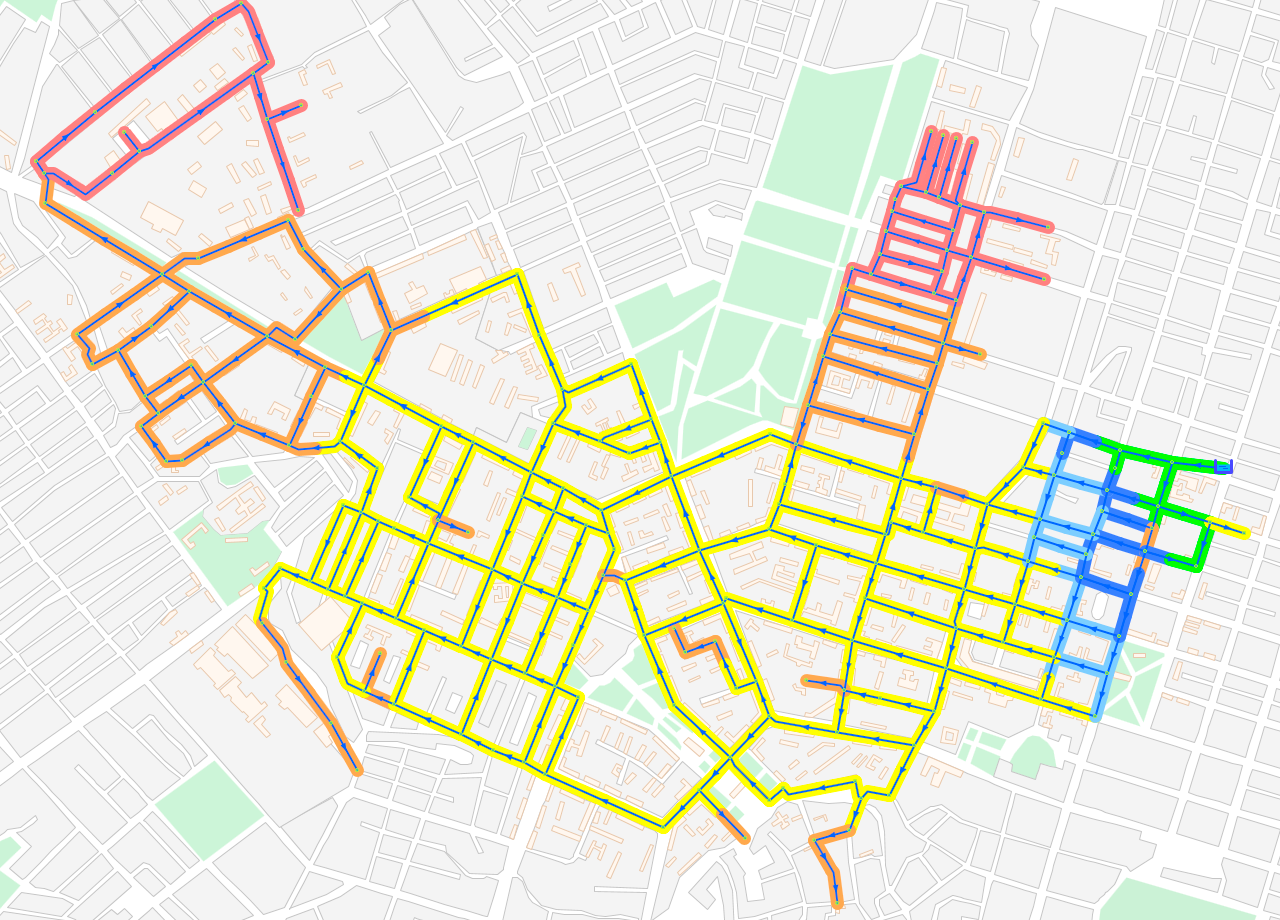
The results of reserve flow capacity calculations can be called a map of spare capacity. They are represented by a set of linear and symbol objects stored in a separate vector layer.
Symbol objects are tie-in points; the corresponding reserve flow rate, pressure at the point, diameter and identifier of the input section are stored in attribute tables.
Linear objects can appear in different colors. Linear objects are created on top of water supply system sections; the color of the objects corresponds to custom ranges. The reserve flow rate, pressure at a starting point, diameter and identifier of each section are stored in tables.
Reserve capacity calculations are used when:
- Issuing technical specifications for connecting new consumers
- Identifying disadvantageous water supply areas that do not have any reserves
- Choosing locations for new buildings and constructions projects
- Publishing information on a company’s website in order to increase the investment appeal of a water supply scheme.
Video. Calculating reserve capacity of a water supply system.
More about calculating reserve capacity
See also: Modeling water hammer


